
HMS Victory Model Tutorial
Modelling Ships in Blender: A guide
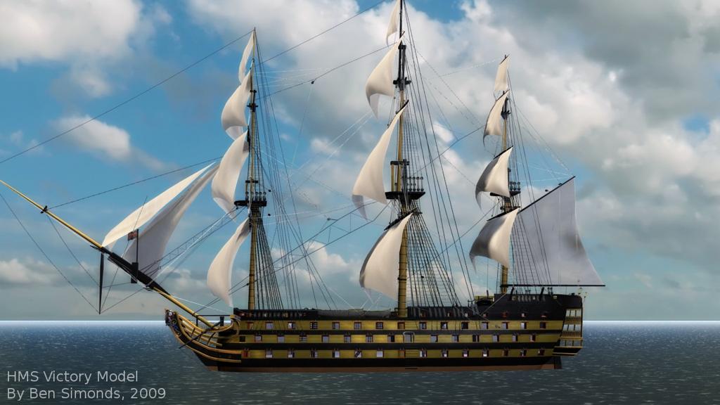
I’ve been interested in the age of sail my whole life - pirates, galleons, the East India Company, but the ships are the stars of the show. Many are works of art in their own right, and so trying to replicate them in 3D can be both a joy and a challenge. I’ve made a few ships in Blender, but my most recent is by far the most ambitious - a replica of the first rate, 100 gun, ship-of-the-line HMS Victory, circa 1805, which Nelson commanded at the battle of Trafalgar. Now that that my model is largely finished, I’ll try and share some of the things I’ve learned in the process.
This will be more of a guide to approaching some of the main problems I came across, than a step-by-step tutorial, but it should be useful for more than just building another HMS Victory replica as a result. I’ll go over the main challenges in the construction and how I overcame them. I will probably assume a small level of blender knowledge, such as how to extrude, move, scale, rotate etc, but I will try and include anything I think isn’t obvious.
Part 1. Reference
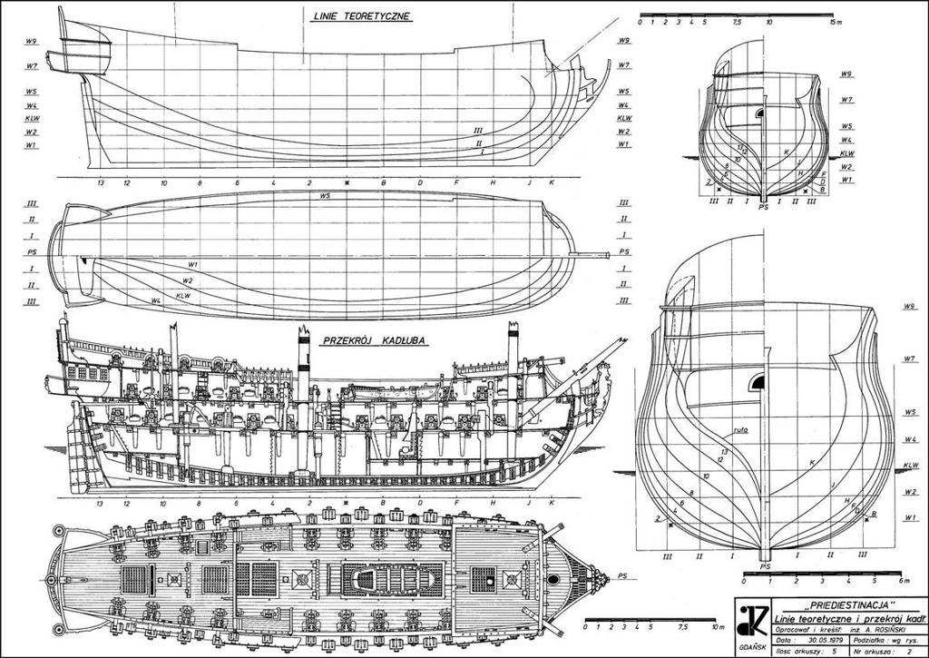
Reference is the most important part of the whole project in my opinion. For something as complex as this you can’t have to much of the stuff, and so with that in mind I went off to trawl the internet, and came back with plenty of photos, facts and figures concerning my project. Some of it is specific to the Victory, but a lot of it is general shipbuilding stuff as well. I include some links to the latter: ChapmanNet features wonderful plates from an 18th century book on ship making called Architectura Navalis, by Fredrik Henrik af Chapman, and blueprints for a wide array of ships and other things can be found at the-blueprints.com.
Part 2. Blocking Out
This is the next important stage, particularly as I didn’t have specific blueprints for the victory. I knew the measurements though, and so I set about converting as much of the technical details into rough models as I could, working from photos either as just inspiration, or where I could as background images inside blender. I put in the rough cross sectional lines of the hull using line drawings of other boats from the same era, and the outline of the ship and height and length of the decks from reference photos. The cross sectional lines were modelled as curves, and give a good approximation of the shape of the hull, as well as being useful later on as curve deform paths for creating the frames. The outline of the hull was modelled with curves as well, and the decks as polys. It’s all fairly simple stuff, but very useful later on. 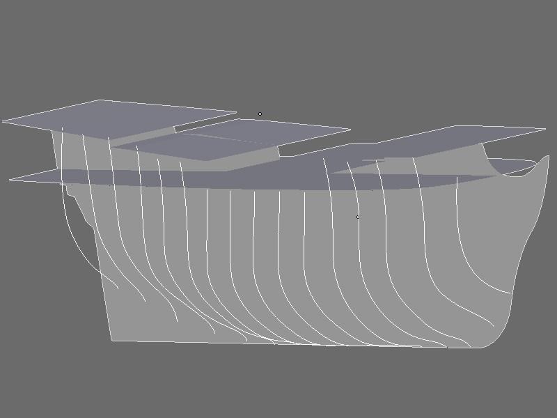
Part 3. The Hull
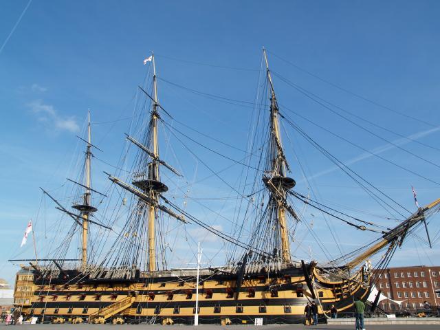
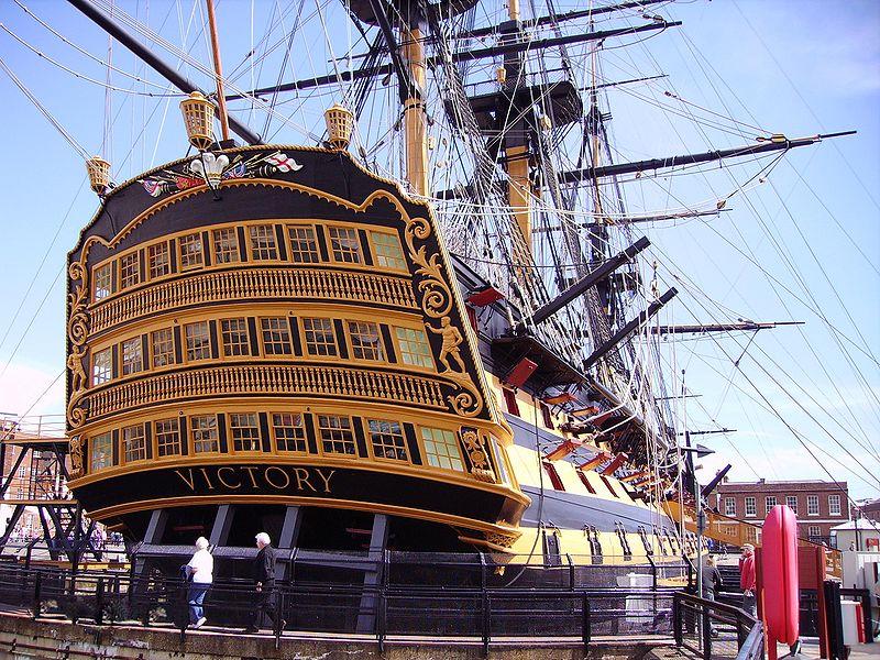
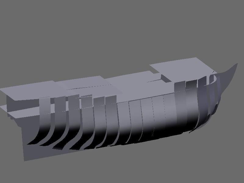
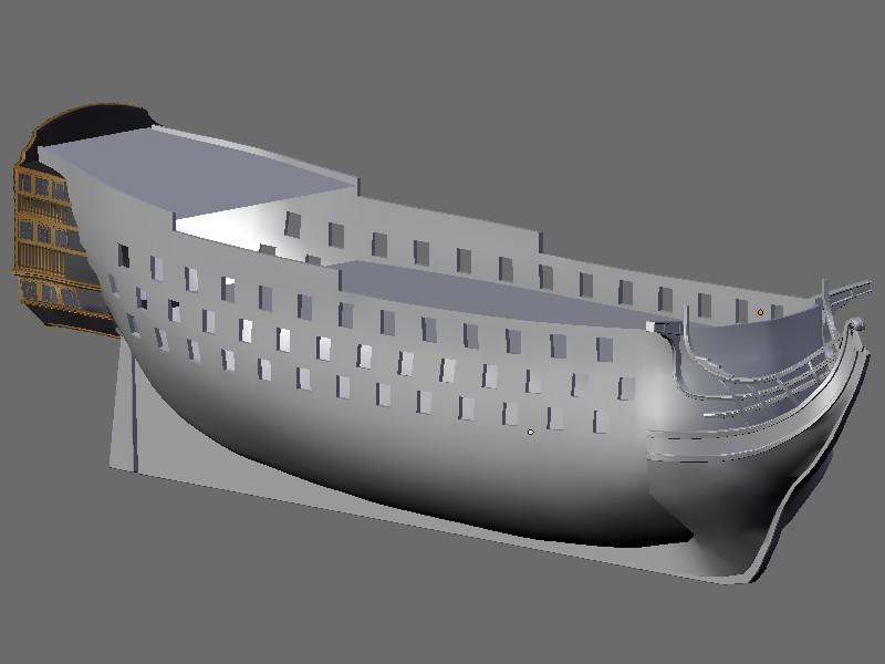
Making the hull is difficult for ships with portholes, as not only does the hull have to flow nicely in its form, there have to be holes in the right places too for the cannons. As a result getting clean topology can be a nightmare. I went through a number of revisions with the Victorys hull, and whilst the final version still isn’t perfect I’m pretty pleased with the results. Note that I did not subsurf the hull, so getting straight edges around the portholes was not an issue. This also saved on resources at rendertime and I think did not affect the quality of the model overall. Step 1. Construct the hull using whatever means you like, focussing only on the shape. Many people prefer NURBS surfaces for this sort of thing, which I’ve used for other projects. Indeed if you have good line drawings for the ship you want to make this is probably the ideal method, but poly modelling sufficed here. and I had plenty of guides already thanks to the blocking out stage so I went with those. This will not be the final hull, so don’t worry about topology too much. Step 2. Create the topology for the portholes and planking on a flat plane and retopo it onto the already constructed original hull. This allows you to get nice neat and regular topology without too much trouble. Specifically it avoids having to use nasty boolean modifiers, which create terrible topology around holes - avoid at all costs. Simply model the surface of the ship as a flat grid and cut away the areas where you want your portholes. Then retopo this using “retopo” -> “retopo all” buttons in the mesh buttons panel. Inevitably you wont be able to cover the whole surface of the hull in this way, so once the main flat areas of the hull are covered, complete the rest in retopo mode over the top of the original hull. This can then be mirrored, and extruded to give the hull some thickness.
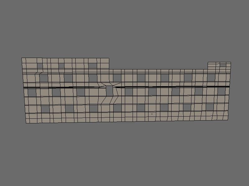
Basic flat layout of the side of the hull.
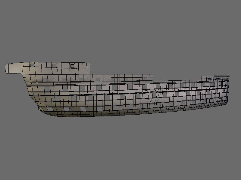
Rotopo’ed onto the original hull shape (not visible)
Mirrored and extruded to give the final shape.
Part 4. Skeleton
This step is optional, given that you might not be interested in showing the inside of the ship. Of course, if we were constructing the ship in real life, we would have to do this first. But in 3d we can make the hull first and then use that as a guide for the frames and other supporting structures. I think this is the easier way. If you made curve guides based on the line drawings of the ship as I did (see blocking in), then these make excellent starting points. Simply create a long bevelled cuboid as a base, then subdivide it along it’s length and use the curve to deform it to the correct shape. Technically, this doesn’t give quite the right shape at the base of the frame, but given that this is is unlikely to be seen, I wasn’t too concerned about this. Floor Joists then span across the ship between the frames, and usually in the gaps between the frames as well. Once again - use your reference!
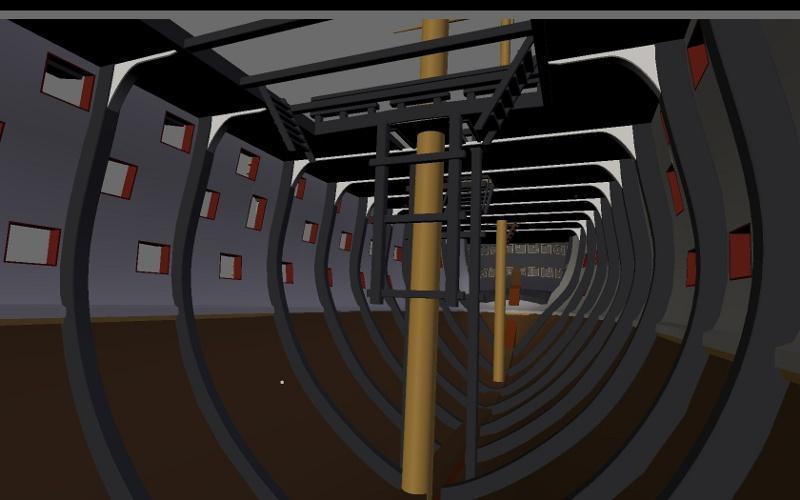
The frames on the inside of the ship.
Part 5. Stuff, and lots of it
Well, you now have all the basic parts of the ships body. The hull and the skeleton. The decks are almost done too, as they were roughed out in the blocking stage , but you still have plenty of work to do! The decks of the ships are covered in stuff - cannons, ropes, lanterns, stairways, holes, railings, gratings. Not to mention the masts, the figureheads, support craft - the list is endless! It’s up to you to make them, as it’s far beyond the scope of this tutorial to tell you how to do them all. It’s just a matter of ploughing through really, no tricks here.
Part 6. Rigging (The ship variety, not the animation variety)
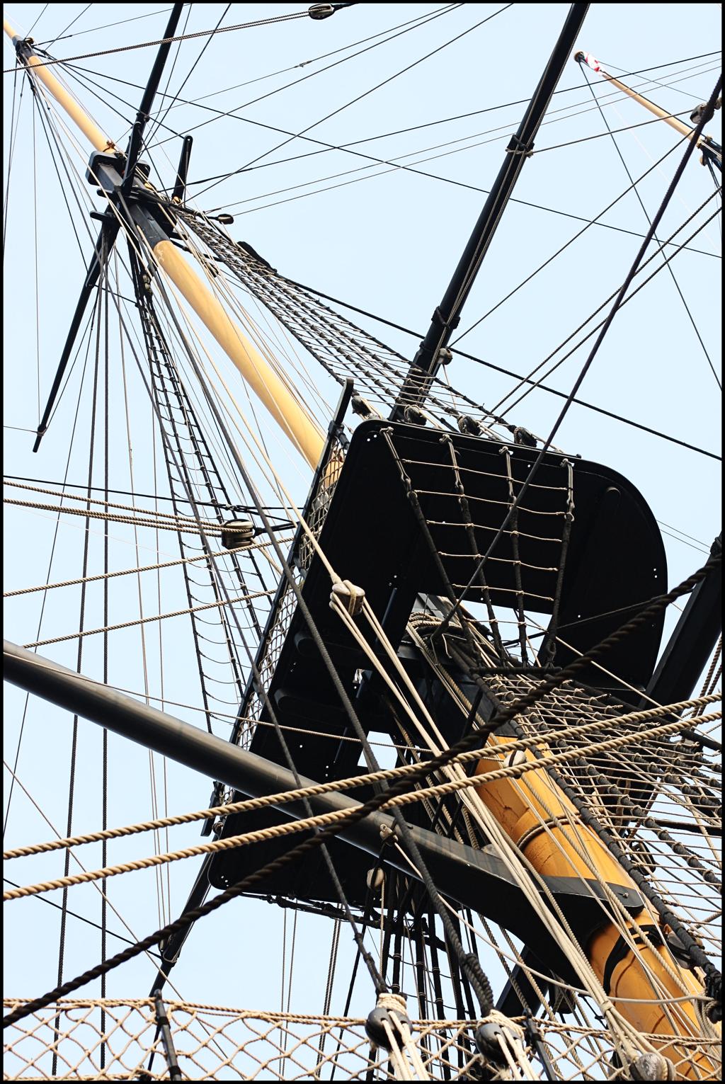
This is the long part. Seriously. The Victory had approximately 26 miles of rigging, and whilst I didn’t replicate anywhere near that amount in my model, the amount that I did do took a long time. The most efficient way to achieve the rigging in Blender in my opinion is to use paths. Most of the rigging consists of straight (or slightly bowed due to gravity) sections of rope with sharp bends where it goes through a block or pulley. Thus using paths with a low “U” order - two or three depending on the amount of slack in the rope, allows you to create the ropes whilst placing a minimum number of points. Your reference will be invaluable here, as finding out where each rope goes through and where it ends is a major task and unless you’re a in expert in rigging, you wont know without looking through any photos you have. I collected some extra reference at this stage for just this purpose.
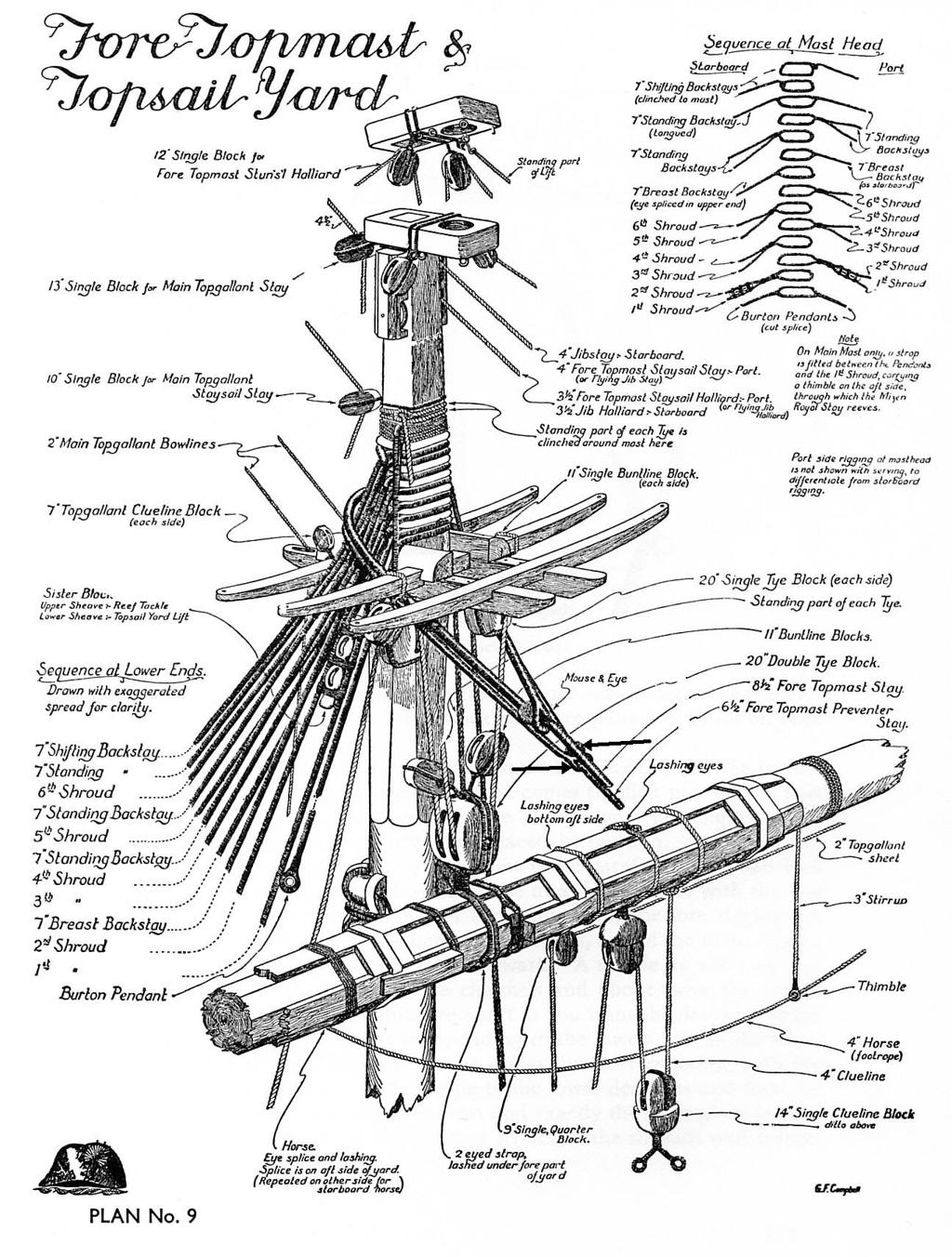
Rigging Reference
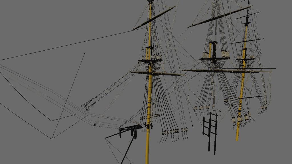
Rigging: There’s a lot of it.
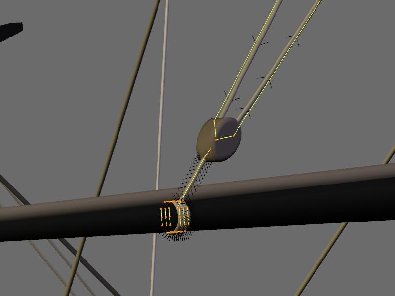
Modelling the rigging with paths.
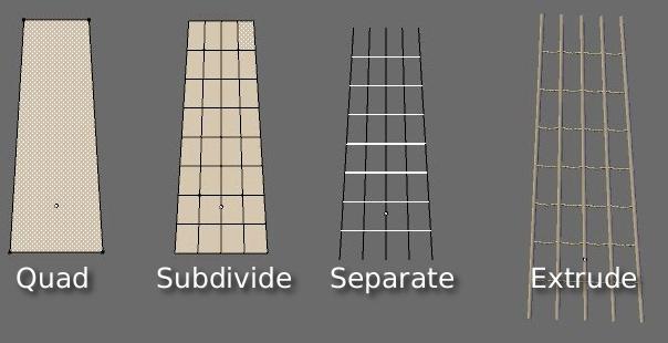
One exception to this approach is the shrouds, these are the nets that allow sailors to climb up to the crows nests. Modelling these was driving me mad, trying all sorts of approaches, until I came up with a neat little way to do it. Start out with a single polygon quad that covers the whole area of the shroud you want to make. Then subdivide it’s edges by the number of ropes you want to have. So divide it into four along the horizontal edges and say twelve on the vertical edges if you want four vertical ropes and twelve horizontal ones. Then sepatrate the two sets of edges by selecting them all the vertical edges with edge loop select (atl+shift+RMB), followed by part selected (P). Do this for the horizontal edges as well to get two separate sets of edges. These can then be extrued into ropes by selecting all the edges in your new mesh, extruding them back once, and then selecting everything again and extruding up (or sideways). This gives the ropes some volume. You can also give the horizontal ropes some slack by subdividing them again and moving the new vertices down a bit. Finally recombine (ctrl+J in object mode) the vertical and horizontal ropes to get a mesh that you can move and deform with proportional editing into whatever shape you need without messing up the places where the ropes join!
Part 7. Textures
Textures for this project were entirely photo-based, using photos from CGtextures.com. Various photos were combined and layered to create the different surfaces, and almost all were then made seamless in order to allow for repetition across the large surfaces like the decks and the hull. For example for the painted planks texture on the outside of the hull, a wood texture was used as a base layer, followed by a paint layer (masked by a scratchy grunge texture to let the wood show through in places), followed by some grunge textures and finally a some dark lines to give the impression of wooden planks. The bump map was created using the same texture, but with the planks layer emphasised over the other layers. To make the textures seamless I simply used offset the image (ctrl-shift-O in GIMP) and cleaned up the edges. This give much cleaner results than the “make seamless” plugin. This process was used for most of the textures on the Victory.
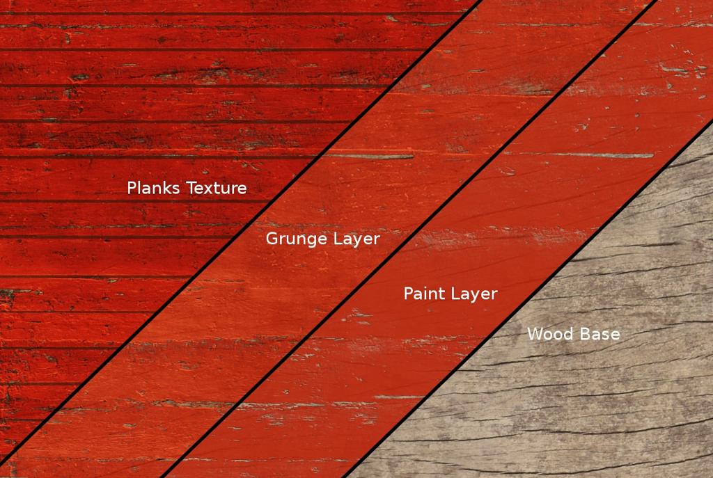
Wood Texture Breakdown
Part 8. Scene
Creating a convincing seascape is difficult, as out at sea the view stretches out right to the horizon. Replicating this in 3d requires some trickery. For the rendered turntable I created a floor plane that stretched out only in front of the camera, and had this parented to the cameras motion. This plane was bent slightly up at the end to avoid having to have it stretch on forever; the key is to make this subtle so as no to affect the materials too much. The materials were mapped to a stationary empty, so that the camera and floor plane rotated together, but the material stayed stationary. The material consisted of a sky texture mapped to the reflection coordinates of the floor plane to emulate reflection of the sky, and some hard noise cloud procedurals to affect the normal value (and some displacement in the foreground) of the waters surface and give some nice foamy white wave peaks. Blenders atmosphere settings for sun lamps were used to give the brightness at the horizon. The turntable was rendered in separate passes - one for the ship, one for the sky, and one for the sea, plus z-buffers and an ID mask for the sea, these were all saved to .exr files in the multilayer zip format, so that the could easily be played with later - I tend to do my compositing in a separate .blend file to the scene I’m rendering. These were then composited afterwards in Blenders node editor with some adjustments to gamma and some glow.
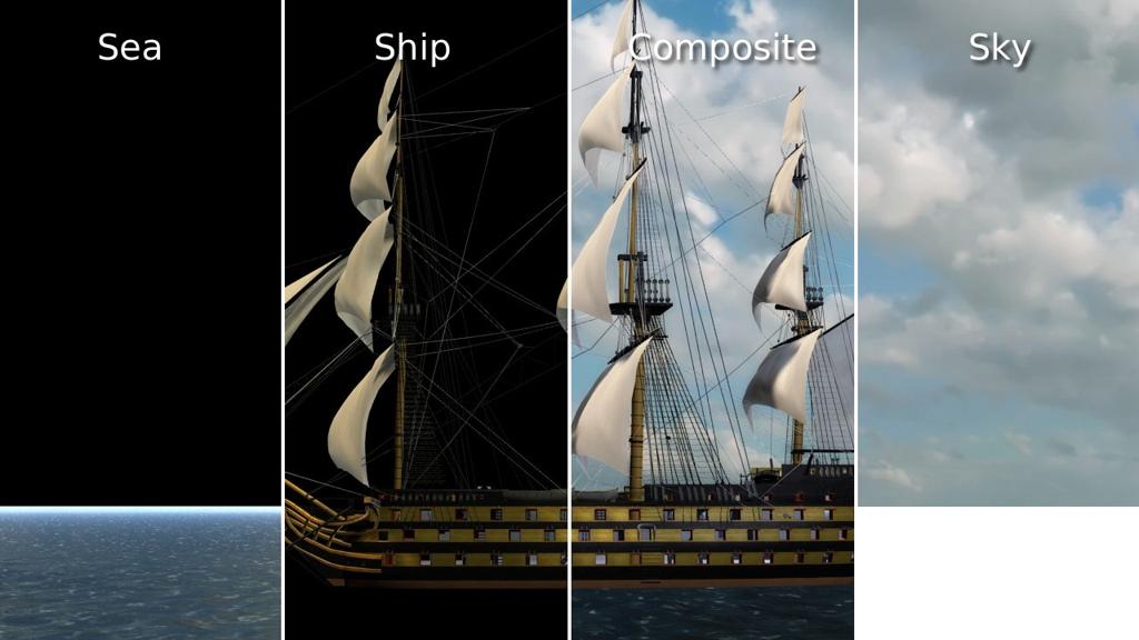
Breakdown of the Rendered Turntable.
Conclusions:
Well, I hope that was useful. If you have any questions leave a comment and I’ll try and add it to the tutorial. I apologise for the small images, that seems to be what WordPress allows, but the full WIP thread at BlenderArtists.org has larger images and many more of them too.
Comments
Ovidiu (Sep 04, 2009)
I’ve been struggling to make the keel and fail for a long time to get a good result - thank you for sharing this technique!
Rodrigo m. (Jan 31, 2010)
I would really like to see a little more indepth on your wood texturing technique, or at least a reference to wich brush pack you used, for the results are just amazing and looks really simple to do…
Carmen A. (Jan 10, 2010)
This looks like a very good resource for not just modellers, but anyone remotely interested in the Age of Sail.
Great work and thank you for sharing!
bensimonds (Mar 15, 2010)
I didn’t find one in my search for reference, but you never know.
Ramona (Mar 15, 2010)
I would love to know if there is a blueprint around for the rigging of the HMS Victory.
herupriadi.co.cc (Jun 08, 2010)
thanks for ur information :)
stefanobeck (Jul 29, 2010)
Your model is a very good job.
Larry (Jun 01, 2011)
Any animations for the blood? ;-) But fair do’s mate, that is one serious challenge, glad you had your own personal victory with it :-)
Neveah (Sep 19, 2011)
Tip top stuff. I'll eexpct more now.
Alex (Aug 21, 2012)
Brilliant! I’m working with Legos, but your tutorial works brilliantly. Thanks.
flam1ngdem0n (Oct 17, 2013)
Thanks a lot. I did not know if it was the same for the Victory or not. But thanks for the image link! Really appreciate the help!
Ben Simonds (Oct 17, 2013)
Did you mean this one? /images/old/plan02.jpg
It’s not actually of the Victory, but a similar ship. I used it for reference in a couple of places where I couldn’t get exact reference though.
flam1ngdem0n (Oct 17, 2013)
Sorry, when I said Keel I meant the Bow of the ship. Does anyone know where I can get a good blueprint images of the bow of the ship so I can use it for modeling? Or maybe the original poster can upload the images somewhere?
Thanks and much appreciated
flam1ngdem0n (Oct 17, 2013)
I plan on working on a very detailed model of the HMS Victory myself. The only issue is that I can’t seem to find a blueprint that shows the front of the ship (the keel I think its called) that I can use for modeling. Except…here.
The issue I seem to be having with the one posted on this page, is that it is a very low resolution. Does anyone know where I can get the same blueprint drawing, but at a high resolution so I can reference it?Thanks
marcusm00 (Sep 22, 2014)
I’m so glad I found this page! I’m working on a model of the USS Constitution and this has helped a lot. Great work!
reidhb (Feb 26, 2018)
No images on site you linked to why that. P.S, I bot your book.
Français (Jun 21, 2018)
« … replica of the first rate, 100 gun, ship-of-the-line HMS Victory, circa 1805, which Nelson commanded at the battle of Trafalgar. »
Please note that the Victory was the ship in which vice-admiral Horatio Nelson was during the battle of Trafalgar, but he commanded the whole English Fleet there, not the Victory herself, which captain was Thomas Hardy.
Jovzin (May 24, 2015)
Hello I do not undertand the rigging part.
What were you rigging ? As far as I know rigging is mainly for body of human or animal. But you were rigging the ropes ?
Ben Simonds (May 25, 2015)
Rigging: http://en.wikipedia.org/wiki/Rigging
Anon (Mar 19, 2016)
Why not use the skin modifier to make the shrouds
Djmax (Dec 06, 2016)
Can you explain Part 3 in detail please? Mostly because in Blender 2.78 there is no Retopo All… At least from what i searched. and also the hull… So basically all of part 3 please?
clive (Oct 17, 2016)
can you give me the dimensions of a port hole for victory please Ive made a version of victory full size to scale in secondlife in prims, I can walk the decks and fire the cannon
uncategorized — Mar 18, 2009